Cover of Make: 93 - How to Train Your Robot
This project appeared in Make: Vol 93. Subscribe for more maker projects and articles!

We are building a small dispenser for all kinds of cereals. Of course, this useful helper can also be used to dispense small portions of M&Ms and other sweet treats, which should quickly win the hearts of the other family members. The interesting thing is that we only need a few parts: A servo, glass panes, a few screws, 3D-printed parts, and a controller.

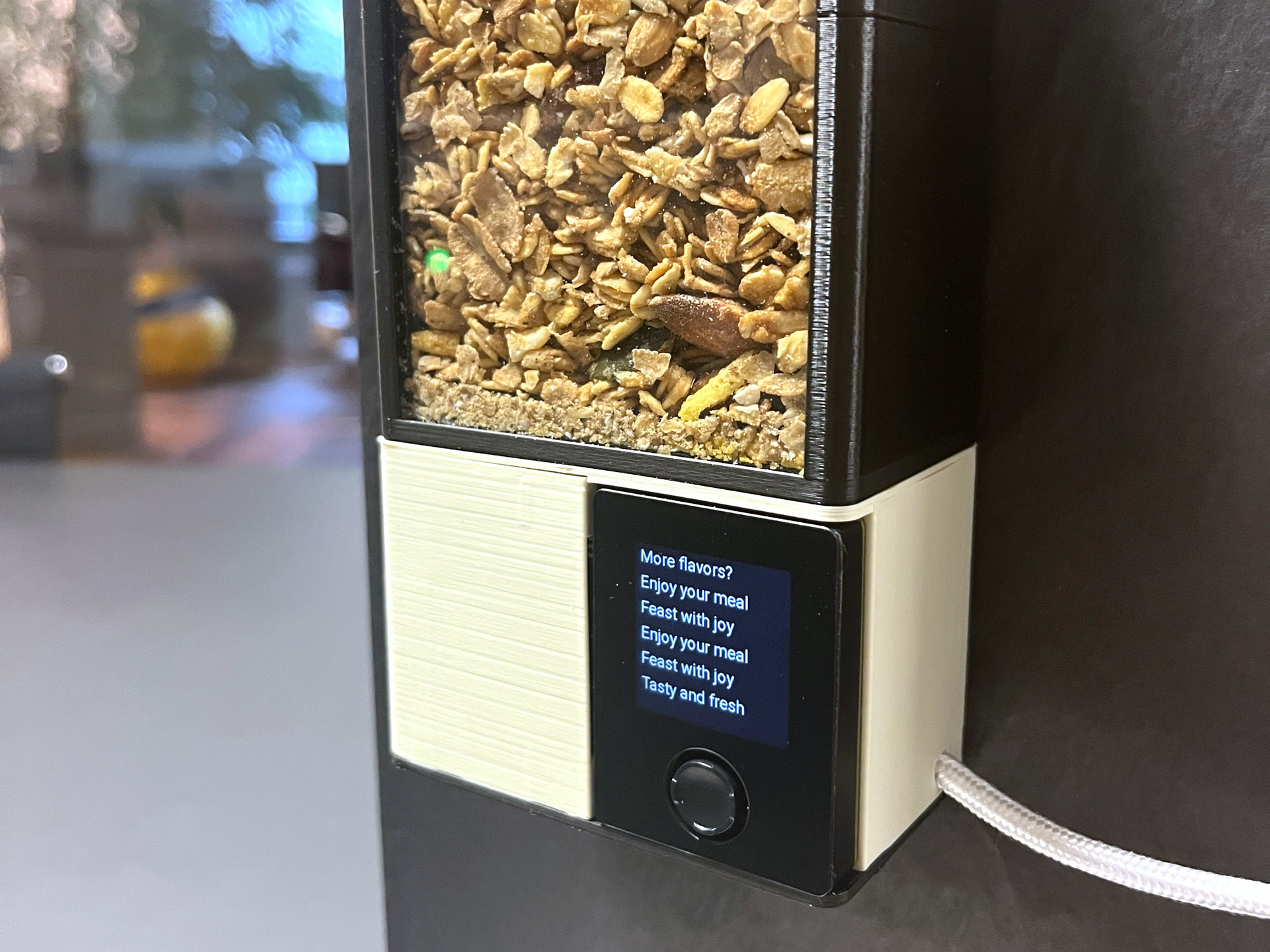
This project contains a servo-powered dispenser mechanism consisting of a bucket which can eject small portions of the loaded material. The housing is made of glass, and can of course be made as large as required in your own projects. We have opted for a compact housing shape here. As soon as everything is assembled, the device can be brought to life via a microcontroller. At the push of a button, the desired food is patiently portioned into the bowl, with a side order of mechanical noises.

A particular challenge of this project was using a commercially available servo for the dispenser mechanism. This makes the project easier, and also cheaper. If we exclude the microcontroller, the components cost less than $20!

Once again, we are using the Oxocard Connect in this project. The special feature here is that the microcontroller is not permanently installed in the device. We use the cartridge slot to make it modular, so that the Oxocard itself can be used for multiple projects.

The Oxocard Connect brings the device to life. Plug it in and you’re ready to dispense your snack!

Servos are more maker-friendly

If you want to build something with motors as a maker, you quickly face various challenges. Motors need power, which immediately raises the question of the power source. How should they be dimensioned? They also cannot be controlled directly with a microcontroller; additional motor controller electronics are required to convert the digital signal from our computer into movement. Then we have the problem of the gear ratio and the axes. There are countless variants of both. This always overwhelms me. I’ve bought a few motors before, but they usually don’t fit exactly when I want to make something.

Servos are much easier. They can be controlled digitally directly via pulse-width modulation (PWM). There are also standard servo sizes that various manufacturers adhere to to some extent, and the mechanical transmission takes place via levers, whereby various sizes are supplied. Servos have many advantages if you want to try something out. In our project we are using an SG92R. This is an inexpensive micro servo which we’re pushing to the limit, but it works quite well. One of them is included in the Innovator Kit, though it is worth getting several. These are available from various suppliers for little money. They can be used in a variety of ways and have a good price/performance ratio.

Mechanical structure

There were various setbacks and challenges during the construction of this model.
Certainly the transportation of the material is the number one problem. There are various ways of portioning bulk material. In our case, we are dealing with bulky, grainy and crumbly material. The products also differ massively. Generally speaking, the smaller the pieces, the better it works. For example, I was able to transport Rice Crispies reliably and without any major blockages. With the Crunch cereals with nuts, there were a few unusual cracking and crunching noises that worried me. However, the machine survived these too. But blockages cannot be ruled out and sometimes you have to use your fingers or a screwdriver to help a little.

The shape of the cup and the tub is round — inspired by a ball valve. The bulk material enters the cup via gravity, then the cup is tilted 180° with the servo.

Flaky and lumpy material, so-called bulk goods, are transported in industry using screw conveyors or shakers, among other things. In our case, we use a mixture of a gravity feeder and a bucket. I was also inspired by a ball valve design. This is the mechanism often used in more modern water mixers. The bucket is designed so that there is no center bar, allowing us to transport as much volume as possible.

After many tests, it turned out that the size of the bucket is crucial. It must of course be larger than the largest piece to be transported. However, the mechanism works better if the ratio is 1:1.5 or even 1:2. The more irregular the pieces are, the more often blockages occur.

Large, misshapen pieces also tend to get caught in each other so that gravity alone is no longer sufficient to transport the pieces into the cup. The solution here was to position the axle in such a way that the bucket’s blade edges penetrate the bulk material, allowing it to be moved. So we scrape around a bit until the “mass” flows again.

The bucket protrudes into the container, so it can dislodge locked material and set it in motion again.

What will the next generation of Make: look like? We’re inviting you to shape the future by investing in Make:. By becoming an investor, you help decide what’s next. The future of Make: is in your hands. Learn More.

Project Steps

Preparation: Printing, Cutting, and Some Sanding

The project has a few challenges that I would like to address. We start with the preparation. We have a small mechanotronic machine here that combines various disciplines. Let’s look at the 3D-printed parts first.

The alignment of the parts when printing is crucial for strength. This way works best.

After everything is printed, there are two mechanical tests. In the first case, we put the three yellow parts (housing + lid + base) into each other. There are two small knobs on both sides. Depending on the print quality, the matching holes may need to be reworked a little.

For the second test, we place the shovel cup next to the lower part of the housing. This should be able to be turned without much force. You can then put the four parts of the housing, base, bucket and lid together and check whether everything fits properly.

Glass cutting knives can be bought at any DIY store for little money. Caution: Always wear gloves!

Two glass or PMMA plates are required for the container. If necessary, these can of course also be 3D printed. I used glass sheets between 1.7-2mm thick and cut them to 70 x 100mm using a glass cutter.

We reduce the servo horn to 11mm wide.

We have to cut the servo horn to a width of approximately 11mm so that it fits into our machine.

Assemble the Electronics

Now it’s time to assemble, starting with the electronics. The following parts are required for this step:

  • Oxocard Connector
  • Breadboard Connector Cartridge
  • Servo + servo horn
  • A disused USB-C or USB-A cable
  • 4 M3 flat head screws, approx. 8-10mm long

In this step, we solder the electronics together.

The USB cable will supply our device with power. First, we cut off one of the USB plugs and remove approximately 5cm of the cable sheathing. Of the four wires, we only need red and black. These are usually a little thicker than the other two data lines, which we can shorten slightly. Remove approx. 2-3mm of the sheathing from the red and black wires and tin the ends with a soldering iron.

Of the four wires in the cable, we need only red and black.

The preparation for the servo is similar. We remove the connector, remove the sheathing (only 2-3mm) and tin the ends.

Tin these pads with some solder before you solder the wire connections.

On the breadboard connection cartridge, we also tin the GND pins (top), as well as 5V EXT, 5V, GND and IO01.

Solder The Connections

Feed the USB cable through the hole on the back of the housing.

Now solder the two USB connections: red to 5V EXT, black to GND.

Next, solder the servo cables very tightly to the following pins:

  • Servo brown = GND
  • Servo red = 5V
  • Servo yellow = IO 01

Check your solder joints for faults. Short circuits can permanently destroy the electronics.

Attach the Servo and Circuit Board to the Underside

We now take the bottom part of the housing and place the servo provisionally on the holder.

Then take the circuit board and place it in the holder provided. To prevent it from slipping out, you can fix it in place with a little hot glue or superglue. Make sure that all the cables are on top and nothing is jammed.

Assemble Housing and Base

In this step, we carefully pull the housing over the base. You can pull the housing apart slightly so that the circuit board has room between the two tabs. Make sure that the cables do not get jammed. These are still on top and will be positioned correctly in the next step.

Now try to push the two studs on the underside of the housing together. If it has worked, the board should now protrude about 5mm over the edge and be firmly seated.

Lay the Cables

Position the cables in the space between the circuit board holder and the blade housing.

If needed, use tweezers or a screwdriver to push the two cables down.

Now the most difficult part is done.

Screw On the Bottom

We now fix the bottom of the housing with 4 M3 screws. To do this, we screw on the bottom from below.

Function Test and Alignment of the Servo

Remove the servo from the holder. Insert the Oxocard into the holder and plug the USB cable into a power source. The Oxocard should now start. If this is not the case, check the cable connections again.

Now load the script “Dispenser” from Examples/Publications onto the Oxocard and start the script.

After a split second, the screen displays “Ready for you.” Click on the button and watch the servo align itself correctly. We can now start installing the servo. If nothing moves, check the cables again and try again.

Installing the Servo

Attach the cut servo horn so that it is lengthwise to the servo axis and screw it on. You can see how the shovel has to be attached afterwards.

In this position, the lid is closed. When you click on the button, the shovel turns 180 degrees and picks up new material. Then fix everything in the casing as shown in the picture.

Screw On the Cover

Carefully put the lid on. Again, make sure that the two knobs on the top snap into place. Now you can fix everything with 4 M3 screws.

Congratulations! You did it. The dispenser mechanism is now fully assembled and ready to use.

Click the button a few times and admire your work.

Transfer Script to Device

We will now make a small but important addition. We now store the code directly on the device. If you now switch on the device or insert and remove the Oxocard, the correct script will always be started automatically. To do this, start the NanoPy environment, click on the “Load on cartridge” icon above the script. This transfers the current script to the breadboard cartridge.

Unplug the Oxocard and plug it back in: the dispenser is immediately ready for use :-)

As Big or as Small as You Like

In this tutorial, we will build a small container to show you how it works. You can build this out of plexiglass, as a cylinder, funnel, or as large as you like.

For our small sample container, we place the panes in the edges and glue the lid with a little superglue. We screw the container onto the device with two M3 screws.

You can also attach your own creations above these screws. Finally, we just insert the ramp and then it’s time to install it in the house. On the back, you will find two recesses where you can attach the device with screws.

Software

The program is so short that it’s not worth using ChatGPT for it. It serves as an example and shows how to control the servo. There are countless examples in the NanoPy environment that you can use for extensions. For example, you can add a clock, build a menu where users can store their profile. By connecting to ChatGPT, you can also display cool sayings or give tips on consumption.

Lines 1-3:
Here we import the monitor library, which we use for text output, and configure the servo. We use the PWM protocol for communication. The frequency here is 50Hz.
Line 6 shows how to display a colored message on the screen. “monitor” is a kind of scroll window: when there is no more space, the content scrolls further.

Line 8-18:
To keep things from getting too boring, our cereal vending machine not only spits out grains, but also snappy sayings. Of course, you can customize or add to these here as you like.

Lines 20-29:
These three functions control the shovel. “downState” means the shovel is looking down, i.e. throwing the material out. “upState” tilts the shovel upwards.

The script is perfect for experimenting. We look forward to seeing your extensions.

Lines 31-35:
The event routine is called up as soon as one of the buttons is clicked. In this case, we write a random message and operate the shovel.

Line 37 sets the shovel to the start position

Conclusion

If you happen to already have a 3D printer, these instructions show you that you don’t need a lot of money to make a cool device. Our tip: use servos for your experiments. In the instructions, we use the Oxocard Connect because the adapter allows us to use the controller for several projects. This saves resources and ultimately also the environment. Of course, you can also do all this with a low-priced ESP32 board, button and TFT display if you want to have it permanently. This shouldn’t be a problem for the experienced maker.

The project also has a lot of potential for improvement and expansion. To make it work better with larger items, you can enlarge the mechanism and, if necessary, use a larger servo. However, this will make it difficult to power the device via USB.

Another important thing to remember is that plastic from 3D printers is great for tinkering and experimenting, but less suitable for food without further processing. Use food-grade filaments for printing and/or treat the surfaces with food-grade epoxy spray before use, as the filament can also be contaminated during printing in the machine.

Join our #oxocard Discord channel and let us know what ideas for improvement or expansion you come up with!

This project appeared in Make: Vol 93. Subscribe for more maker projects and articles!

Images by Thomas Garaio