This project appeared in Make: Vol 93. Subscribe for more maker projects and articles!
Making your own safe may seem an unrealistic project, because the same tools that build it can also pry it open or cut it apart. It can never be really — safe!
Still, there is a purpose to this project. If you see no signs that anyone has tampered with your safe, you can feel confident that the stuff inside has been undisturbed. In this way, it provides some peace of mind, besides being fun to build. It’s a perfect weekend project — you can fabricate the safe from sheet aluminum and rivets in about a day, and then wire and install the electronic circuit the next day.
What will the next generation of Make: look like? We’re inviting you to shape the future by investing in Make:. By becoming an investor, you help decide what’s next. The future of Make: is in your hands. Learn More.
Project Steps
Materials
I decided to use aluminum, because it’s so affordable and easy to work with. If you substitute stainless steel, the plans will be the same, but cutting and drilling it will be more difficult, and I think the increase in security will be negligible.
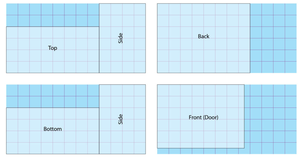
Cutting panels from four pieces of aluminum, each measuring 6″×12″.
Aluminum sheet is easily found online. I bought four 6″×12″ pieces for $20 total. I cut the panels for the safe out of these sheets as shown, where the grid lines are at intervals of 1″. Naturally if you want a larger safe, you can use bigger pieces of aluminum (and the price per square inch will drop significantly).
Although blunted by years or use, these vintage shears can still cut 1/32″ aluminum sheet.
In the United States, sheet-metal thickness is usually measured in fractions of an inch. I chose 1/32″, sometimes described as 0.03″ or 0.8mm. You can cut it with shears, such as the vintage pair shown, or you can use a hacksaw. If you have a band saw with a bimetal blade, that’s the best of all. I don’t like using a circular saw for thin aluminum, because the blade can hook into the sheet and throw it in unpredictable directions.
When working with metal, remember that edges and corners may be sharp. Wear work gloves, and anytime you use a band saw with sheet metal, earplugs are a worthwhile precaution against future hearing loss. After cutting, you can use either a flat file or a deburring tool to clean up sharp edges.
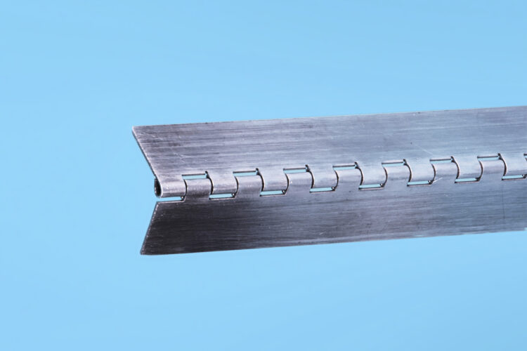
Aluminum piano hinges can be cut to size. You drill your own holes.
I bought piano hinges for my safe from McMaster-Carr. You can trim them to the length that you need, and drill holes where you want them. Amazon has a less expensive but more limited selection.
To connect the panels, I used ½”×½”×1/16″ aluminum angle, giving the safe an impressively rugged look.
Rivets
A riveting tool pulls the mandrel until it snaps off.
I held everything together with pop rivets, also known as blind rivets. If you’ve never worked with rivets, they are calibrated in two ways: the thickness of the body, and the length of the body, which should be at least 1/8″ longer than the combined thickness of materials that the rivet will penetrate. Above, you can see rivets on the underside of a piece of plastic, before and after being installed.
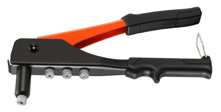
A typical hand-powered riveting tool.
Rivets are quick and easy. Drill a hole, insert the rivet, pull its mandrel with a riveting tool, and the head of the rivet makes the body swell up, securing it without any need to get access to the underside of the material. The mandrel breaks off, leaving the head of the rivet looking neat and smooth. Cordless electric riveting tools are easier to use, but expensive.
A cordless electric riveting tool.
Solenoid-Operated Latch
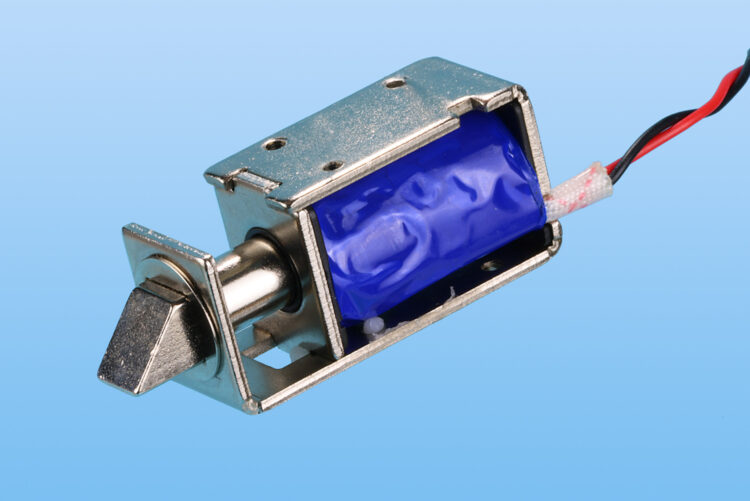
A 12V latch contains an electromagnet inside the blue wrapper.
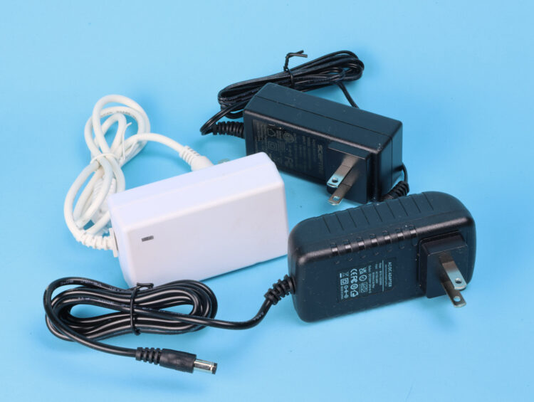
For the lock on the safe, I found the latch shown above. It uses a 12V solenoid — an electromagnet containing a sliding plunger. The power supply can be any AC/DC adapter rated for at least 2A.
A selection of 12V AC adapters.
Attach the latch to the inside of the door so that the triangular catch flips inward when you close the door and the catch meets the frame.
Electronic Components
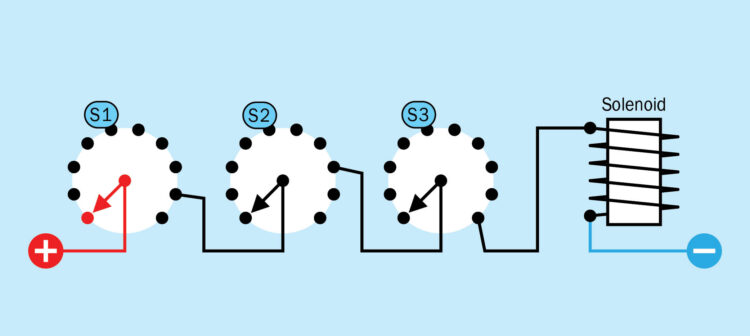
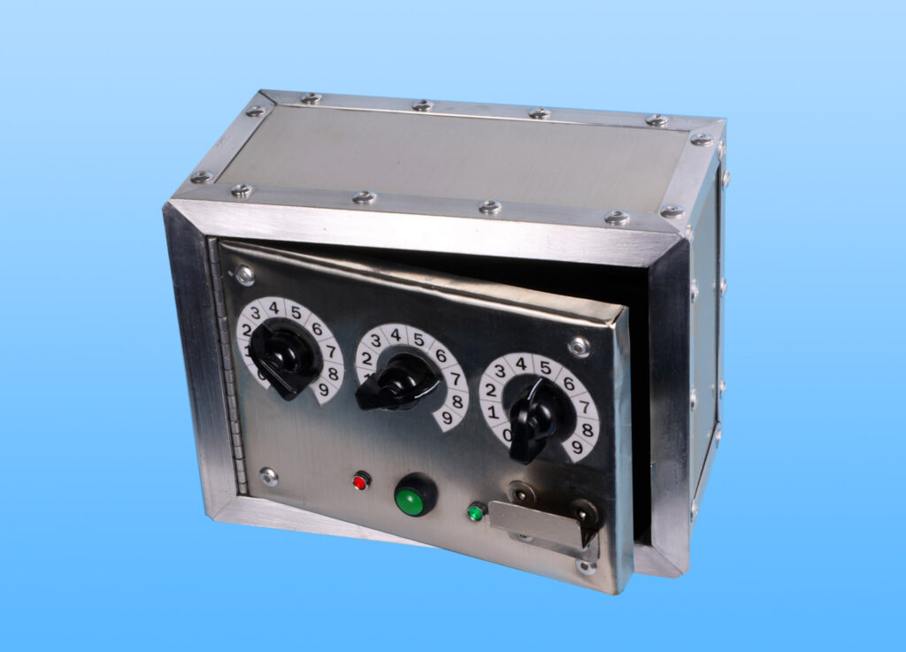
Three rotary switches, wired to allow only one combination that activates the solenoid.
I wanted a three-digit passcode to secure my safe, and rotary switches are an ultra-simple way to enable this, using the circuit above. One contact on each switch is wired to the pole of the next switch, so that all three switches must be in their correct positions to activate the solenoid. You now have an ultra-simple combination lock.
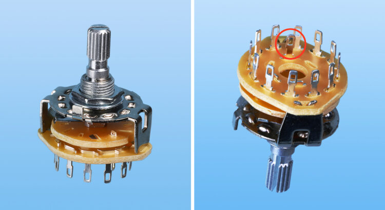
A 10-position rotary switch. The circled solder terminal is the pole of the switch.
This rotary switch has a knurled shaft, while others may have round or D-shaped shafts that vary in diameter. Make sure you get knobs that match.
Unfortunately, my system of switches has a disadvantage: It is vulnerable to a “brute-force” attack. A safe cracker simply tries every permutation of switch positions, listening for the lock to open. This may seem laborious, but turning the switches to their 1,000 possible permutations can take less than 10 minutes. Even if you have four switches (10,000 permutations), a brute-force attack is still doable.
How could I prevent such exploits? At first I considered the system used by websites, which may block you after three or four failed attempts to enter a passcode. I liked this idea, but it would require a logic circuit, and I wanted something simpler. I decided to have a button that must be pressed to open the lock, with a 10-second delay before the circuit will allow you to make another attempt.
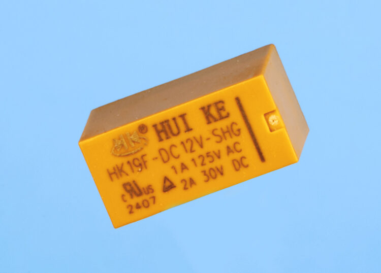
A typical relay appropriate for a breadboard. It measures about 1″×½”.
The word delay made me think of that most ancient and fundamental friend of makers everywhere, a 555 timer. The original version is ideal for this project, as it can deliver up to 200mA. This is still not sufficient to power the solenoid, but can drive a small signal relay of the type shown, which takes about 120mA. The output of the relay is rated at 2A, which can activate the solenoid.
Best of all, the timer, the relay, and the solenoid can all share the same 12V power supply, whereas a microcontroller would require 3.3V or 5V and would be sensitive to voltage spikes.
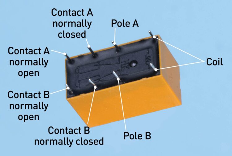
These relay pin functions are typical, but check the datasheet. For this project, only the coil pins, and Pole A and Contact A (normally open), are needed.
When you shop for relays, make sure they have pins spaced in multiples of 1/10″, to fit a breadboard. The typical pin functions for this type of relay are shown here, and I found some on Amazon costing only about $1 each.
The Circuit
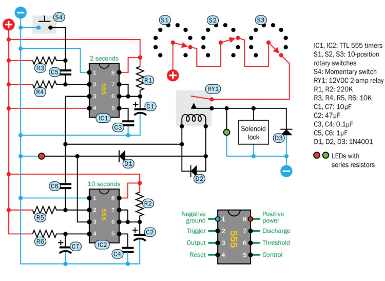
I assembled these components to create the circuit shown. Here’s how it works. IC1 is a timer wired in monostable mode, meaning that it delivers one pulse when triggered. (You’ll find full details about 555 timers on many websites, or in introductory books such as my own Make: Electronics.) The pulse from pin 3 of IC1 goes to relay RY1, which connects the rotary switches with the solenoid, which opens the lock if the rotary switches are in their correct positions.
Schematic for the electronic safe. The three rotary switches are shown in their correct positions to open the lock.
The pulse from the relay coil is grounded in pin 3 of IC2. Pin 3 is the output pin of IC2, but this timer hasn’t been triggered, yet, so its output voltage is low, which means it can sink current.
The 2-second pulse from IC1 that goes to the relay also goes to C6, a coupling capacitor. At the end of the pulse, the drop in voltage from IC1 draws a tiny jolt of current from pin 2 of IC2, through C6. This triggers IC2, which imposes the 10-second delay. (If 10 seconds seems too long, you can reduce the value of R2 or C2.)
During the delay, IC2 has a high output, so it won’t sink current anymore. No matter how persistently you press the pushbutton, nothing happens, because the voltage on each side of the relay coil is now about the same — until IC2 reaches the end of its cycle.
R3, R4, and C5 are necessary, because if I connected pushbutton S4 directly with the trigger pin of IC1, someone could hold the button down, and the output from the timer would continue indefinitely, allowing multiple attempts to find the right switch combination. Remember that the 555 responds to the level of input voltage, not to a change in voltage. In other words, it is not “edge-triggered.”
R4 keeps the input of IC1 normally high. When pushbutton S4 is pressed, it draws a pulse of current from pin 2 through C5, triggering the timer. When the button is released, R3 equalizes the charge on the capacitor, so that it will enable the next button-press.
As for the diodes: D1 prevents current from flowing backward, through the relay coil, to the low output of IC1, when the output from IC2 is high. D2 and D3 are protection diodes, to shunt the spike in voltage which normally occurs when power to a coil is switched off.
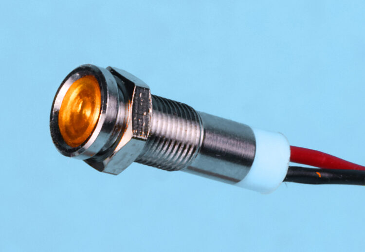
An LED indicator nicely packaged, including a series resistor appropriate for 12V.
My schematic includes indicator lights to show the status of the circuit. These are shown as little colored circles, representing indicators that contain their own resistors, suitable for 12VDC. You can find them on eBay or Amazon. Like many 12V products, they are really intended for people who customize cars.
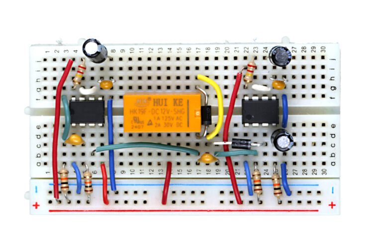
The components fit easily on a mini breadboard.
My complete circuit fits easily on a mini breadboard, and the finished safe is shown below.
Conclusion
Lock ‘Em Up!
The finished safe.
Your safe is now ready to store objects of value, although you have to remember one precaution: After you open and close the door, don’t forget to rotate the switches randomly to conceal your secret combination. Otherwise, the safe won’t be safe at all.
Images by Charles Platt
This project appeared in Make: Vol 93. Subscribe for more maker projects and articles!
Our websites use cookies to improve your browsing experience. Some of these are essential for the basic
functionalities of our websites. In addition, we use third-party cookies to help us analyze and understand
usage. These will be stored in your browser only with your consent and you have the option to opt-out. Your
choice here will be recorded for all Make.co
Websites.